BOILERS AND STORAGE BOILERS
PUFFER COMBI
- USE: The combined system of this flywheel-producer is made up of a receiver and a distributor of energy, produced by various traditional or alternative sources, directly or indirectly, through exchangers inside the flywheel. The hot water necessary to feed the different types of heating systems is taken from the flywheel. It will be at high temperature when the taking takes place in the upper part of the flywheel. It will at low temperature for radiant floor systems when the water is taken from the lower part . In this system, the preparer-storage tank for domestic hot water is inside the flywheel.
- CONSTRUCTION:S235JR EN10025 quality steel sheets, assembled and welded with the use of automatic controlled atmosphere systems. Fixed spiral heat exchangers (depending on the models) with S235JR EN10025 steel pipes welded to the tank.
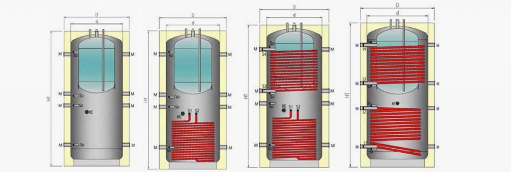
art. KOMBI flywheel-manufacturer without fixed exchangers, preparer-accumulation for DHW in enamelled steel (EMAIL).
art. KOMBI 1 SERPENTINO flywheel-producer with a fixed exchanger, preparer-accumulation for DHW in enamelled steel (EMAIL).
art. KOMBI-2 SERPENTINI flywheel-producer with two fixed exchangers, preparer-accumulation for DHW in enamelled steel (EMAIL). - ANTICORROSIVE TREATMENT: Internal vitrification (EMAIL), applied in oven at 860 ° C according to DIN 4753.3, suitable for use and consumption of drinking water pursuant to Ministerial Decree 174/2004 and EEC Dir. 76/893.
- WARRANTY: 5 years against corrosion.
AVAILABLE COLOURS
Grey
HEATING
![]()
0
Pmax (bar)
0
Tmax (°C)
0
Pmax (bar) Heat exchanger
| MODEL PUFK | 220/100 | 330/100 | 600/100 | 800/180 | 1000/180 | 1500/300 | 2000/300 | |
| Thermal fly-wheel nominal Capacity – liters | 220 | 332 | 575 | 796 | 900 | 1462 | 1996 | |
| d | Thermal fly-wheel effective Capacity – liters | 120 | 232 | 472 | 621 | 743 | 1167 | 1605 |
| Domestic Storage effective Capacity – Liters | 100 | 100 | 100 | 175 | 175 | 295 | 295 | |
| d | Diameter no insulation – mm | 500 | 500 | 650 | 790 | 790 | 790 | 1100 |
| D | Diameter with insulation – mm | 600 | 600 | 750 | 990 | 990 | 1150 | 1300 |
| HT | Total height – mm | 1385 | 1860 | 1910 | 1805 | 2105 | 2320 | 2390 |
| Lower Coil Exchange Surface – m² | 1,4 | 2 | 2,4 | 2,6 | 3 | 4,1 | 4,5 | |
| Higher Coil Exchange Surface – m² | 2 | 3 | 3 | 4,5 | 4,5 | |||
| k | Tilting Height – mm | 1495 | 1916 | 2014 | 2058 | 2281 | 2535 | 2668 |
| CONNECTIONS | ||||||||
| M | Domestic circuit inlet | G1 ¼” | G1 ¼” | G1 ½” | G1 ½” | G1 ½” | G1 ½” | G1 ½” |
| RE | Connection for thermal fly-wheel electrical resistance | G1 ½” | G1 ½” | G1 ½” | G1 ½” | G1 ½” | G1 ½” | G1 ½” |
| sf | Fly-wheel Air Hole | G ½” | G ½” | G ½” | G ½” | G ½” | G ½” | G ½” |
| So | Connection for pipe | G ½” | G ½” | G ½” | G ½” | G ½” | G ½” | G ½” |
| sf | Connection for Air Hole | G ½” | G ½” | G ½” | G ½” | G ½” | G ½” | G ½” |
| S1-S2 | Inlet-Outlet Lower Coil | G¾”M | G¾”M | G¾”M | G¾”M | G¾”M | G1 ¼ | G1 ¼ |
| S3-S4 | Inlet-Outlet Higher Coil | G1” | G1” | G1” | G1 ¼ | G1 ¼ | ||
| TANK CONNECTIONS | ||||||||
| Es | Cold water inlet | G¾” | G¾” | G¾” | G¾” | G¾” | G¾” | G¾” |
| Us | Hot water inlet | G¾” | G¾” | G¾” | G¾” | G¾” | G¾” | G¾” |
| RC | Connection for Domestic Circuit | G¾” | G¾” | G¾” | G¾” | G¾” | ||
| A | Connection for Magnesium Anode | G1 ¼” | G1 ¼” | G1 ¼” | G1 ¼” | G1 ¼” | G1 ¼” | G1 ¼” |
| TECHNICAL DATA | ||||||||
| PE | Thermal Fly-wheel Max Pressure – bar | 6 | 6 | 6 | 6 | 6 | 6 | 6 |
| PC | Testing Fly-wheel Max Pressure – bar | 9 | 9 | 9 | 9 | 9 | 9 | 9 |
| TE | Max Temperature of fix coil – °C | 100 | 100 | 100 | 100 | 100 | 100 | 100 |
| PST | Thermal Fly-wheel Max Pressure – bar | 3 | 3 | 3 | 3 | 3 | 3 | 3 |
| PCS | Testing Fly-wheel Max Pressure – bar | 4,5 | 4,5 | 4,5 | 4,5 | 4,5 | 4,5 | 4,5 |
| Puffer combi empty weight – Kg | 85 | 110 | 140 | 180 | 220 | 270 | 330 | |
| One coil Puffer combi empty weight – Kg | 95 | 120 | 150 | 210 | 250 | 300 | 360 | |
| Two coils Puffer combi empty weight – Kg | – | – | 190 | 230 | 270 | 340 | 390 |


